CENG 469 Advanced Graphics Final Project
Update 2022-11-01: The code of this project has been released at this Github Repository. Pre-built Linux binary is also available here with required assets.
As explained in the previous post, I chose compute shaders as my final project topic for CENG 469 Advanced Graphics Course. In this post, I will showcase what I have developed so far. I will also briefly explain some technical challenges I had to overcome.
For an elementary introduction to compute shaders, please see the previous post first.
Base Program
I have been following the Vulkan Tutorial Website by Alexander Overvoorde in order to learn the basics of Vulkan.
Unlike the tutorial, I used vulkan.hpp but the API is almost the same. So, it was easy to follow along.
Moreover, I used TinyGLTF library for loading models from .gltf files instead of .obj format.
It’s not directly relevant to my project, but .obj models always felt like a huge limitation for anything non-trivial in my previous graphical programs.
Thanks to this endeavour, I also gained more experience with Vulkan, which I desperately needed to tackle the actual project.
For example, I learned about push constants to render a glTF file.
In order to learn about TinyGLTF usage, compute shaders, and other Vulkan related topics, I made extensive use of Sascha Willems’ Vulkan repository, as well as Vulkan Samples repository by Khronos Group. Without these resources and Vulkan Tutorial, my project wouldn’t be possible.
In Vulkan Tutorial, all of the code is in a single C++ file that contains a monolithic class. At first, I found it difficult to organize the Vulkan code in my project. But as I implemented new features, common patterns naturally arose and I abstracted these patterns to separate structures.
In the previous homeworks of this course, we used a simple Makefile for the build system since these programs were much simpler. However, I wanted to follow a more scalable approach with this project. Thus, I used CMake for configuring and building the project. Virtually any non-trivial C/C++ application uses CMake or a similar build system, including the Vulkan samples I referenced above. Furthermore, using CMake allows me to easily add external libraries to my project, and even make them optional. Speaking of which, ImGui is the first optional dependency I added to my project.
ImGui Integration
Dear ImGui is an immediate mode GUI library for C/C++. Despite having minimal dependencies, it’s quite capable and popular. Even if you don’t know about it, it’s highly likely that you have seen an ImGui user interface before.
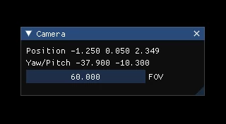
I previously used hard-coded keyboard shortcuts to interact with my graphical programs. This approach is quite cumbersome and makes it hard to modify variables at run-time, especially floating point variables. With ImGui, it’s ridiculously easy to create a good-looking and functional user interface:

This is the corresponding code snippet:
ImGui::Begin("Camera", &showCameraSettings);
ImGui::Text("Position %.3f %.3f %.3f", position.x, position.y, position.z);
ImGui::Text("Yaw/Pitch %.3f %.3f", yaw, pitch);
ImGui::DragFloat("FOV", &fov, 0.5f, 10, 180, "%.3f");
ImGui::End();
Of course, before being able to use ImGui like this in your application, you first need to integrate it to your graphics pipeline.
Before that, you need to add ImGui to your build system, which is quite easy with CMake.
Here, I added an option to enable/disable ImGui with a flag in my main CMakeLists.txt:
option(USE_IMGUI "Enable Dear Imgui for a nice graphical user interface" ON)

if(USE_IMGUI)
    add_subdirectory(libs/imgui)
    list(APPEND EXTRA_LIBS imgui)
    list(APPEND EXTRA_INCLUDES "${PROJECT_SOURCE_DIR}/libs/imgui")
    add_compile_definitions(USE_IMGUI)
endif()
With this setup, ImGui source files should be located in libs/imgui folder with the following CMakeLists.txt file:
file(GLOB IMGUI_SRCS "*.cpp")
add_library(imgui ${IMGUI_SRCS})
Now you can easily enable or disable ImGui dependency while configuring with CMake.
Whenever you are writing ImGui-specific code while programming your application, you need to surround that part with #ifdef USE_IMGUI and #endif so that it doesn’t get compiled when ImGui is disabled.
Likewise, you can use #ifndef USE_IMGUI to get the opposite effect.
Although ImGui’s official repository contains many examples about how to integrate it to your program, I mainly used this article from VkGuide to render ImGui with Vulkan, because it’s the simplest tutorial I could find about this. I won’t go into the details since it’s already explained in the previous links. If you already have a minimal Vulkan application that can render a triangle, adding ImGui is not that hard.
Emitter Particle System
At this point I had a base Vulkan program with ImGui and glTF capabilities. It’s time to utilize the GPU for tasks other than graphics. I started this journey with a simple use-case: particle systems.

In this basic particle system, the particles are emitted from a single point with a random velocity. When they reach a boundary, they are simply reset, i.e., emitted again from the center point.
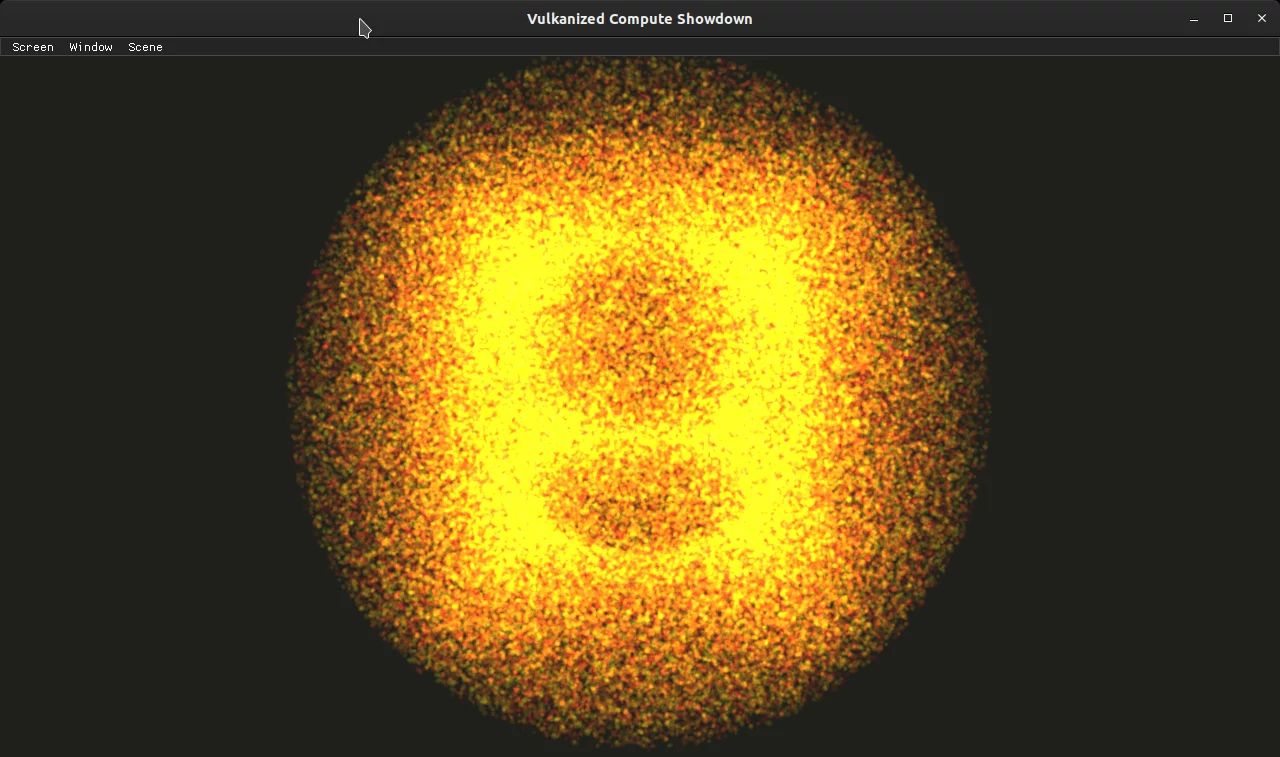
Each particle contains position and velocity information. Graphics pipeline takes the output of compute pipeline and uses it as the vertex buffer, from which it renders points. These points are combined with additive blending. Without additive blending, we would need to implement depth sorting for proper transparency. Since there are thousands of particles condensed into a small region, most of the particles become occluded when they are rendered without transparency.
Here’s a psuedo-code for additive blending:
outputColor = alpha*newColor + backgroundColor;
Contrast that with the usual blending function:
outputColor = alpha*newColor + (1-alpha)*backgroundColor;

The particles don’t interact with each other, so it’s highly parallelizable. Even on my Intel HD Graphics 630 integrated GPU, we can simulate over one million particles with 50 FPS.

A uniform buffer is used in compute shader to pass delta time information (how long has passed since the last frame) and other variables that can be modified in real-time using ImGui interface. If you allow multiple frames to be in flight at once as shown in Vulkan tutorial, you also need to have a unique uniform buffer for each frame in flight. Fortunately, the validation layer will warn you even if you forget about this.
Here’s a video, but beware that video compression is especially hostile towards this kind of videos:
Compute Pipeline
I created a class to separate the compute pipeline from the graphics pipeline, called ComputeSystem in code.
This class abstracts away most of the details of creating a compute shader pipeline, such as SSBO (Shader Storage Buffer Object) and uniform buffer creation, thereby it eliminates boilerplate code.
Although I extended this class to support multiple compute shader passes in the upcoming sections, a single pass is enough for this particle system.
Compute shader pipelines are easier to create than graphics pipelines. However, the hardest part was synchronizing the graphics pipeline with the compute pipeline. We first need to use semaphores to ensure sequential execution between compute and graphics, similar to how the semaphores are used to synchronize rendering and presenting operations. But this is only the start.
Since SSBO of compute shader is used as vertex buffer in graphics pipeline, we need to make sure that graphics pipeline doesn’t read data before compute shader updates them. Similarly, compute shader shouldn’t overwrite any data while vertex shader is reading it. In Vulkan, this is accomplished using pipeline barriers.
In addition to reverse-engineering the code from Vulkan samples, I used this article by AMD GPU Open and this blog post to learn about pipeline barriers. In the pipeline barrier, we specify the appropriate pipeline stages and the buffers that need to be synchronized.
Since the compute shader is oblivious to the graphical stages of the pipeline, we cannot use the vertex input stage in our pipeline barrier; doing so will result in an error by the validation layer. Thanks to the Vulkan specification, I found out that draw indirect stage is the earliest stage in graphics pipeline, and it can be referenced from the compute shader pipeline.
Queue Families
In Vulkan, each GPU can offer multiple queue families, to which we can submit our command buffers. Not all queue families can perform all tasks, some of them are specialized for certain use cases. For example, I have the following queue families in my GTX 1050 device, with the corresponding supported operations:
- Queue Family 0: Graphics, compute, transfer, present
- Queue Family 1: Transfer
- Queue Family 2: Compute, transfer, present
It’s completely possible to write your Vulkan application using a single queue, since any queue family that supports graphics must also support transfer operations. But that’s not the most optimal approach in many cases. For example, using dedicated transfer queue families (e.g. queue family 1 above) can be much more performant compared to using a single queue for everything. 1
Even if you add the capability to use multiple queue families to your program, make sure that your application can run when only one queue family is present. The device driver is not obliged to present more than one queue family. For instance, Intel HD Graphics 630 on my system has only one queue family.
As you can see, queue family 2 in my system specializes in compute operations. Therefore, I reasoned that it might be more optimal to use it for compute shader pass.
Contrary to my initial expectation, this didn’t give better performance. In fact, it was worse when a separate queue family is used for compute. In one test case, performance dropped from ~240 FPS to ~150 FPS. I checked my synchronization code many times to ensure that it’s correct by comparing it to the Vulkan samples. I didn’t spot any mistakes.
I think using multiple queue families in this case might be actually detrimental because the compute and graphics pipelines are highly dependent on each other and need to be run sequentially. Without such restrictive requirements, we could achieve better GPU utilization by using multiple queue families.
N-Body Simulation
N-body simulation approximates the motion of particles under the influence gravitational forces. Gravitational force between 2 particles with masses \(m_1\) and \(m_2\) is given by the following formula, where \(G\) is the gravitational constant:
\[F = \frac{G m_1 m_2}{r^2}\]The constants in this formula can be customized via specialization constants in the simulation, as well as the work group size.
You might have noticed that simulating this will take \(O(n^2)\) complexity instead of the previous \(O(n)\) since each particle interacts with every other particle. In addition to that, we need 2 compute shader passes this time. Because the force calculation depends on the positions of the particles, which should remain constant in the meanwhile. We can update the positions of the particles after updating the velocities of each particle.
The compute shader passes are as follows:
- Gravitational force between all bodies are computed to find the force inflicted on each particle, and the forces are applied to update the velocity.
- The positions are updated using Euler integration.
Although I implemented my own N-body simulation from scratch, I used Vulkan samples repository by Sascha Willems during the process as a reference point.
Shared Memory
The naive way to implement this is to use a loop that iterates through all particles in each invocation to the compute shader. However, it turns out the memory access creates a bottlenech in this case. 2
One way to overcome this is to use a shared memory in each work group. The shader program iterates through the particles array in blocks, size of which are equal to the work group size. Each shader invocation loads the particle at its own offset to the shared memory. After that, all threads iterate through the shared memory array, applying the force from each particle.
To synchronize the writes and reads in the shared memory, we use the GLSL functions memoryBarrierShared() and barrier().
Here’s the simplified code:
for (uint i = 0; i < COUNT; i += LOCAL_SIZE) {
	sharedData[gl_LocalInvocationID.x] = particles[i + gl_LocalInvocationID.x];

	memoryBarrierShared();
	barrier();

	for (uint j = 0; j < LOCAL_SIZE; ++j) {
		applyForceFrom(sharedData[j]);
	}

	memoryBarrierShared();
	barrier();
}
It’s important to note that if your particle count varies, the count of memory barriers in a work group vary as well. This seems to be okay for my nVidia graphics card, but on my integrated GPU (Intel HD Graphics 630), changing the particle count at runtime hangs the GPU and crashes the whole program. Therefore, I didn’t allow the user to change the particle count while the simulation is running. Instead, the pipeline must be rebuilt from scratch.
In the following table, the performance impact of this optimization is shown:
| Particle Count | Dedicated GPU, Naive | Dedicated GPU, Shared | Integrated GPU, Naive | Integrated GPU, Shared |
|---|---|---|---|---|
| 1*2048 | 1875 FPS | 2344 FPS | 880 FPS | 900 FPS |
| 2*2048 | 735 FPS | 960 FPS | 271 FPS | 268 FPS |
| 3*2048 | 460 FPS | 635 FPS | 136 FPS | 136 FPS |
| 4*2048 | 287 FPS | 405 FPS | 81 FPS | 77 FPS |
| 5*2048 | 237 FPS | 306 FPS | 58 FPS | 51 FPS |
| 6*2048 | 149 FPS | 250 FPS | 42 FPS | 36 FPS |
As shown, shared memory provides 66% performance boost with discrete GPU in the last case, a significant increase in the framerate. In all tests, discrete GPU performed better with shared memory.
Surprisingly, this optimization actually slows down the computation a little bit on the integrated GPU in many cases. One potential reason is that allocating shared memory on an integrated GPU might be equivalent to using a SSBO directly, because the integrated GPU uses the host system’s memory anyway. Therefore, when we use the shared memory approach, the driver might just copy data from one part of RAM to the other, creating overhead. Similarly, many operations in Vulkan programming are done with discrete GPU in mind, e.g., creating device local memory and using staging buffers to upload data to it. In integrated GPU, device-local memory is the same as host memory.
Because of such minor yet important details, writing Vulkan code that is optimized for all hardware and platforms constitutes a big challenge.
Instancing
Up to this point, the particles in N-body simulation are rendered using the same point rendering method with additive blending from the previous section. I wanted to render full models for each particle instead.
If I attempted to render these particles in a naive way, this would mean the following:
- Get the simulation state from GPU to CPU.
- SSBO is in GPU-only memory. Copying it to CPU is a huge overhead. Updating SSBO to use host (CPU) memory would also be slow.
- Issue a render command for each particle.
- This means constructing and passing a modeling matrix (or a equivalent structure) to the vertex shader using uniform buffers or push constants.
It’s evident that this approach is gravely inefficient. A much better way to do this is instanced rendering. Since we will render the same model for each particle, it’s pretty much the perfect use-case for instancing.
Again, Vulkan samples repository contains an example for instancing, which was my primary resource for learning.
To my surprise, implementing instanced rendering was easy.
You just bind the instance data as a secondary vertex buffer and use the drawIndexed call.
Of course, before that you need to specify the vertex input attributes and bindings while creating the pipeline.
This time, the input rate of your instance data will be per-instance, as opposed to per-vertex.
This parameter confused me prior to learning instanced rendering because I couldn’t imagine why we would need a vertex buffer with a different input rate.
In vertex shader, the per-instance attributes are passed in a similar manner to the per-vertex attributes. The layout locations must match between your driver program and the vertex shader.
Previously, the SSBO was used as the vertex buffer that contains the point info. Now, the primary vertex buffer contains the actual vertices loaded from the model, and the SSBO is bound as the secondary vertex buffer containing per-instance data.
Furthermore, rendering instanced models instead of singular points did not cause any measurable reduction in framerate. Even on my integrated GPU, N-body simulation maintains ~36 FPS with \(6 \times 2048\) particles regardless of how they are rendered.
Video
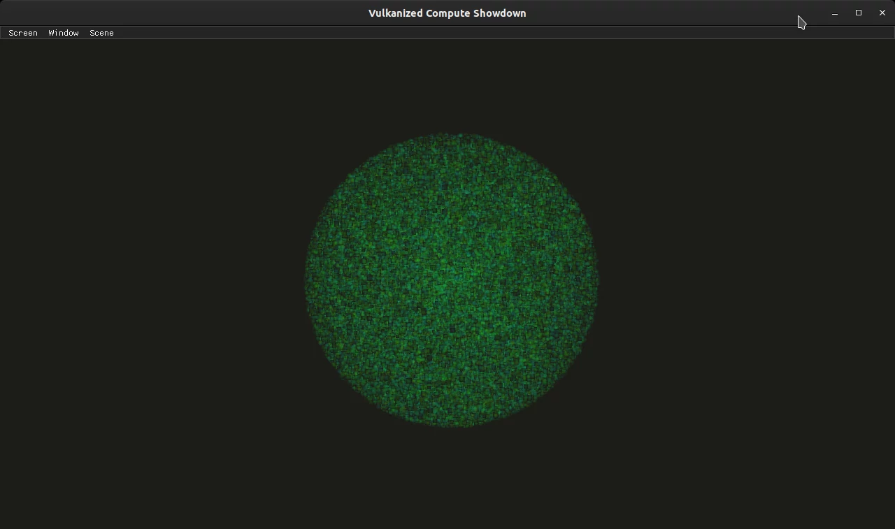
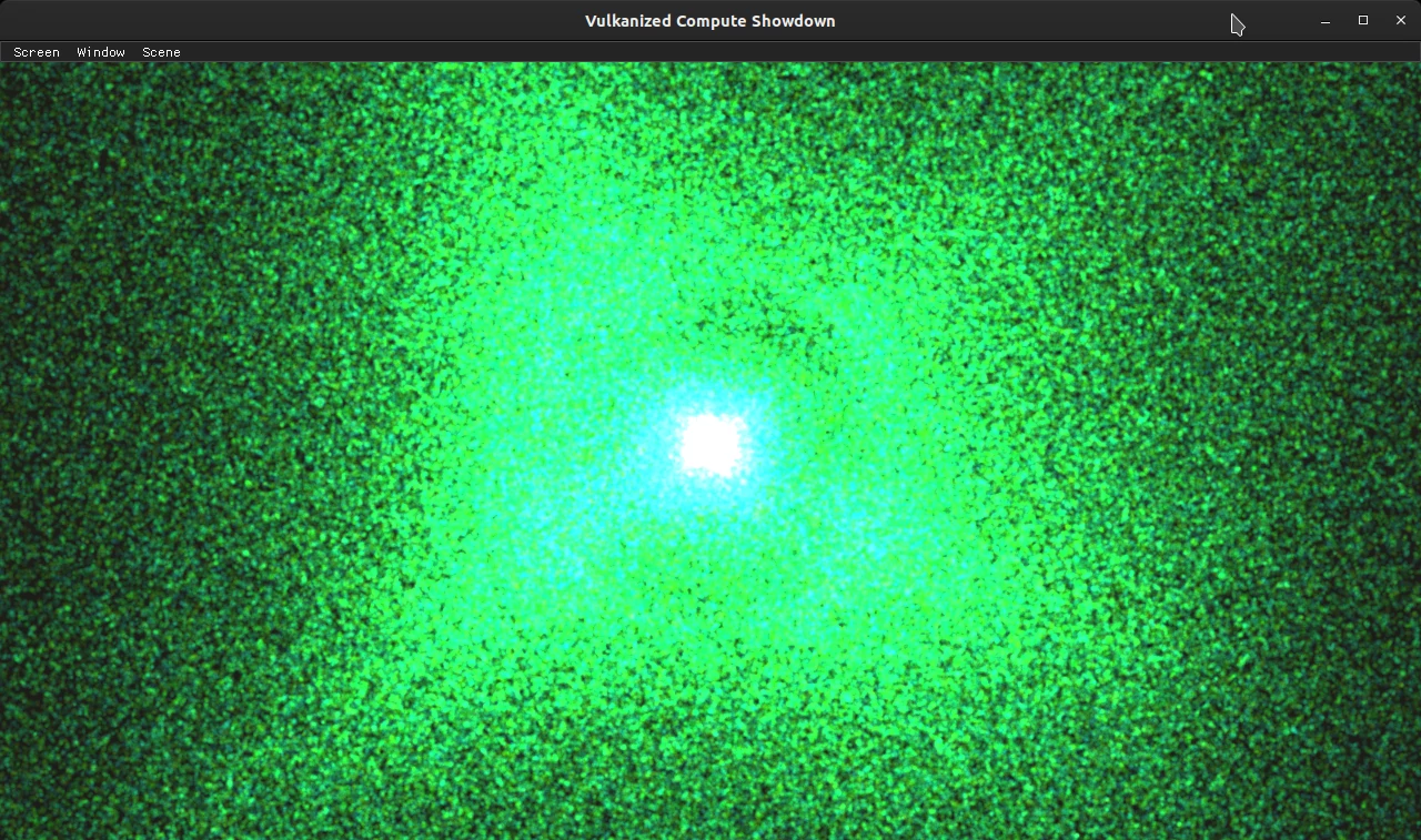
Here’s the full video that demonstrates the N-body simulation:
The individual particles are much more discernible with instanced rendering, and this emphasizes the scale of the simulation. However, this N-body simulation allows the particles to go through each other, which looks quite weird when each particle is rendered as a solid object. At first, I tried adding collisions to the N-body simulation, but this caused particles to clamp together without any interesting interaction. After that I decided to transition into a rigid body simulation.
Rigid Body Simulation
Rigid body simulation is a type of physics simulation that involves unbreakable and inflexible objects. This time, the primary interaction between particles is collision. These two links provide basic physics background for collision response. This document provides a much more comprehensive technical explanation for rigid body simulations.
Similar to the N-body simulation, this simulation also runs with 2 compute shader passes and \(O(n^2)\) complexity.
The basic idea behind solving a physics collision is to separate the velocity of the colliding object to 2 components: one along the collision normal (henceforth \(v_n\)), and the other part, perpendicular to the normal and parallel to the collision tangent (\(v_t\)). In a perfectly elastic collision without friction, \(v_t\) stays the same, and \(v_n\) flips its direction so that it points away from the colliding object. Note that there’s no actual collision if \(v_n\) already points away from the other object. \(v_t\) is only affected by friction, if any.
In a rigorous collision response calculation, masses of the objects and the coefficient of restitution play a role in determining the force and the impulse. But I used a more simplified formula with various assumptions, e.g., all objects have the same mass. Despite that the simulation looks convincing. Furthermore, modifying the formula and adding more properties to objects is trivial since the foundation is already there.
Angular properties (e.g. rotation, angular velocity) of the objects are ignored for simplicity (or rather due to lack of free time), and all objects are rendered as spheres using instancing.
Here, you can watch the rigid body simulation in action:
Conclusion
I couldn’t do everything I wanted in the span of this project since it clashed with the finals week and other course assignments. I plan to continue this project in my free time to see what’s possible. For example, the complexity of the simulations can be reduced using spatial partitioning. Alongside that, the look of the simulation can be improved with the glTF models.
This project marks the end of my journey with CENG 469 Advanced Graphics course. This was one of the most enjoyable courses I have taken during my undergraduate years. Because the topics were interesting, we had lots of flexibility with our implementations and plenty of room for experimentation. Moreover, this blog was first created thanks to this course. Special thanks to the course staff for their efforts.
-
See this StackOverflow question for further discussion on using multiple queue families. ↩
-
See this article for further reading. It explains fluid simulations but contains an interlude on N-body simulations. ↩